


AVR Projects
- Content:
DiSEqC-Tester - Testing Device for DiSEqC-Switches

This is my first AVR-project on this page. The DiSEqC-Tester allows to test DiSEqC-switches that uses 1.0 or 1.1 protocols. (DiSEqC-Switches with 2.0 and 2.1 protocol have backwards compatibility with 1.0 & 1.1 respectively and also may be tested). The device every second sends a DiSEqC-message that makes switch a DiSEqC-switch. Four LEDs are intended to show on/off state of ports of a DiSEqC-switch.
- Features:
- Power supply is 12VDC, max 200mA
- Ports quantity to monitor - 4 (using internal LEDs)
- Protocol support DiSEqC 1.0, DiSEqC 1.1 (Write Port Group Commands)
- Two levels of 22kHz-tone - 650mV, 300mV
- Switch frequency - 1Hz or 2Hz (depends on firmware version)
- Commands indication via LED blinking and sound
- Short circuit protection with sound indication
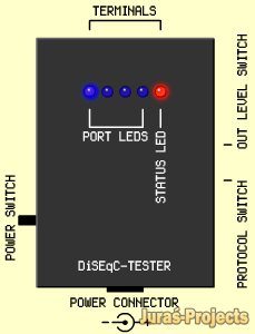
To test a DiSEqC-switch you must connect the red wire with "Receiver" input of the switch, blue wire with case, connect remaining yellow wires to ports of the switch in any order. Choose the protocol, tone-level and then turn power on. If the DiSEqC-switch is OK, a blue LED of the tester will be switching every second to another blue LED with short red LED blinking and beeping. Next photo and video shows how it looks.

The DiSEqC-Tester with a DiSEqC-switch 1.0 (video):
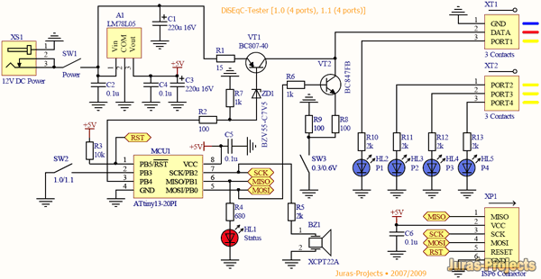
The heart of DiSEqC-Tester is AVR microcontroller ATtiny13-20PI, with clocking from internal RC-generator at 4.8 MHz.
Enlarge image
(Old schematic)
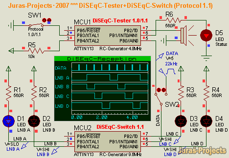
Testing in Proteus with DiSEqC-Switch 1.1 Model:
The device every second generates a DiSEqC-message which has duration of 54ms. Each message consist from 4 bytes. Byte is 8 bit + 9-th odd bit. If protocol 1.0 is used, then device sends next commands-sequences: $E01038C0, $E01038C4, $E01038C8, $E01038CC, $E01038C0 and so later, else $E01039F0, $E01039F1, $E01039F2, $E01039F3, $E01039F0... These commands are so called "Write Port Group N0" (38h) and "Write Port Group N1" (39h) by DiSEqC-Protocol. The full description of DiSEqC-Protocol can be found at web site. For example, DiSEqC-Message $E01038C0 switches port "LNB1" of DiSEqC-Switch 1.0/2.0 into active state.

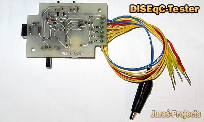
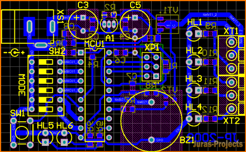
The DiSEqC-Tester board in P-CAD:

The DiSEqC-Tester board view:

![]() DiSEqC-Tester firmware v1.0a (protocols 1.0, 1.1; Frequency 1Hz, no pause after power on).
DiSEqC-Tester firmware v1.0a (protocols 1.0, 1.1; Frequency 1Hz, no pause after power on).
![]() DiSEqC-Tester firmware v1.0b (protocols 1.0, 1.1; Frequency 2Hz, pause 0.5s after power on).
DiSEqC-Tester firmware v1.0b (protocols 1.0, 1.1; Frequency 2Hz, pause 0.5s after power on).
![]() DiSEqC-Tester board in P-CAD 2004 format
DiSEqC-Tester board in P-CAD 2004 format
DiSEqC-Tester+ (used ATtiny2313)
New version of the DiSEqC-Tester using ATtiny2313:

Enlarge
![]() DiSEqC-Tester_T2313_rev_A - DiSEqC 1.0 (4 ports), 1.1 (8 porst), 1.2 ("west", "east"). After every 4-th/8-th command - large pause (for protocols 1.0 and 1.1). No large pauses in 1.2-protocol mode. The archive contains some diagrams.
Number of port-LEDs may be variable, for example 8 or 10, and depends on type of your DiSEqC-Switch.
DiSEqC-Tester_T2313_rev_A - DiSEqC 1.0 (4 ports), 1.1 (8 porst), 1.2 ("west", "east"). After every 4-th/8-th command - large pause (for protocols 1.0 and 1.1). No large pauses in 1.2-protocol mode. The archive contains some diagrams.
Number of port-LEDs may be variable, for example 8 or 10, and depends on type of your DiSEqC-Switch.

DiSEqC-Tester v2 - DiSEqC-Tester with 22kHz tone support
In fact, this device is a DiSEqC-generator, that generates standard DiSEqC-messages. This version of tester is able to provide the 22kHz between the messages, if enabled by DIP-Switch. The DIP-Switch is intended to select protocol and mode you need. Also the DiSEqC-Tester v2 has an improved short circuit protection. Additionally, the 22kHz tone support allows you to test an 22kHz-switch. The DIP-switch allows to select DiSEqC level, type of framing byte and few other capabilities (see schematic diagram). The button is used only in manual mode, when the tester sends a message after button pressing.
Schematic diagram:

Enlarge image
PCB of the DiSEqC-Tester v2:
Assembled DiSEqC-Tester v2:

| Bill of materials (BOM) of the DiSEqC-Tester v2 | ||||
|---|---|---|---|---|
| Designator | Name/Value | Footprint | Description | Quantity |
| A1 | LM78L05 | TO-92 | 3-Terminal Positive Voltage Regulator | 1 |
| BZ1 | XCPT22A | d=16.5mm | Green Electronics Piezoelectric/Ceramic Sound Transducer | 1 |
| C1, C2, C4, C6, C7, C8 | 0.1u 25/50V | SMD 0805 | Ceramic Capacitor | 6 |
| C3, C5 | 220u 16V | d=8, h=11.5mm | CapXon LZ Series Capacitor | 2 |
| HL1-HL4 | LED | d=3mm | Blue LED | 4 |
| HL5 | LED | d=3mm | Green LED | 1 |
| HL6 | LED | d=3mm | Red LED | 1 |
| MCU1 | ATtiny2313-PU/PI | DIP20 | 8-bit Microcontroller with 2K Bytes In-System Programmable Flash | 1 |
| R1, R7 | 10k | SMD 0805 | Chip Resistor | 2 |
| R2 | 15 | SMD 0805 | Chip Resistor | 1 |
| R3 | 1k | SMD 0805 | Chip Resistor | 1 |
| R4, R8 | 100 | SMD 0805 | Chip Resistor | 2 |
| R5, R6 | 560 | SMD 0805 | Chip Resistor | 2 |
| R9, R10, R11, R12 | 2k | SMD 0805 | Chip Resistor | 4 |
| SW1 | 0605 | 6x6 | Switronic 06xx Series Tact Switch | 1 |
| SW2 | BS06GR | BS06 - 6pos | BS Series DIP SWITCH | 1 |
| VT1 | BCX53-16 | SOT-89 | PNP general purpose transistor | 1 |
| VT2 | BC847B | SOT-23 | NPN general purpose transistor | 1 |
| XP1 | ISP6CON | HDR2x3 | Atmel Standard ISP 6-pin Male Connector | 1 |
| XS1 | DC10A | DC10A | Cliff PCB mounting pin / ring type with switch connector | 1 |
| XT1, XT2 | 350-3 | 350-3 (3 pin) | Degson 350 Series Terminal Block | 2 |
| ZD1 | BZV55-C7V5/6V8 | SOD-80C | BZV55 Series Voltage Regulator Diode | 1 |
- ATtiny2313 FUSES:
- SELFPRGEN=1 (Self programming disabled)
- DWEN=1 (Debug wire disabled)
- EESAVE=1
- SPIEN=0 (Serial program downloading enabled)
- WDTON=1 (watchdog disabled)
- BODLEVEL=100 (level at 4.3V)
- RSTDISBL=1 (PA2 is RESET, not i/o pin)
- CKDIV8=1 (Divider by 8 disabled)
- CKOUT=1 (Clock output on PD2 Disabled)
- CKSEL=0100 (Internal RC-Generator 8MHz)
- SUT=10
Note that "1" means fuse is unprogrammed.
![]() DiSEqC-Tester v2 firmware (3004 downloads)
DiSEqC-Tester v2 firmware (3004 downloads)
![]() DiSEqC-Tester v2 board (for a printer) (3976 downloads)
DiSEqC-Tester v2 board (for a printer) (3976 downloads)
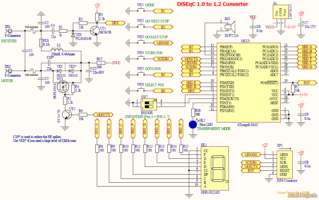
DiSEqC-Converter - Converts DiSEqC 1.0 into DiSEqC 1.2 to control a motor via DiSEqC 1.0
The DiSEqC-Converter is intended for PC DVB-cards which have not support the DiSEqC 1.2 level. Also some cards can work poorly with DiSEqC 1.2. The device decodes DiSEqC 1.0 messages and sends DiSEqC 1.2 messages to a motor. A position corresponds to a port of DiSEqC 1.0. Four positions are possible, because it is the restriction of the DiSEqC 1.0 level. The converter sends a message to a motor when DiSEqC 1.0 port number is changing to another.
- Features:
- A bus powered device (12-20V, 65mA max)
- converts DiSEqC 1.0 into DiSEqC 1.2
- has three modes: normal converting mode (by default), motor control mode and DiSEqC/22kHz-transparent mode
- can drive a motor via buttons
- the buttons (left to right): MODE, GO WEST, GO EAST, STORE POSITION (1 to 7), GOTO POSITION (0 to 7), SELECT POSITION (0 to 7 -> 0..)
- has an additional DIP-switch to "route" command "Port4" to Pos4,Pos5..Pos7 of a motor
- has sound beeper to beep during button pressing
- has 7-segment LED-display to show selected position or DiSEqC 1.0 decoded port
- has resettable fuse to provide overcurrent protection (0.5A)
- DiSEqC-decoder part:
- Framing bytes: 0xE0, 0xE1, 0xE2, 0xE3
- Address Bytes: 0x00, 0x10, 0x15
- Command Byte: 0x38
- DiSEqC-generator part:
- Framing Byte: 0xE0
- Address Byte: 0x31
- Command Bytes: 0x60, 0x68, 0x69, 0x6A, 0x6B
Press and hold the button "GO WEST" or "GO EAST" to drive a motor and release to stop it.

The device is based on AVR ATmega8 MCU.
click to enlarge
The PCB of the DiSEqC-Converter in a design software:

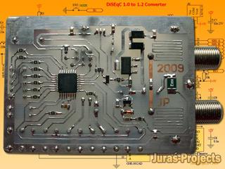
A prototype of the DiSEqC-Converter:

Testing of the prototype in the converting mode (video):
![]() DiSEqC-Converter firmware (1659 downloads) - (the archive also contains a fuse settings file, the schematic diagram and a BOM)
DiSEqC-Converter firmware (1659 downloads) - (the archive also contains a fuse settings file, the schematic diagram and a BOM)
![]() DiSEqC-Converter board (for a printer) (2715 downloads)
DiSEqC-Converter board (for a printer) (2715 downloads)
To be continued. See also
Externally controlled DiSEqC-Generator
The device can generate any DiSEqC-message. Eight DiSEqC-messages are stored in EEPROM of MCU. The length of a message can be three to six bytes. Also the generator is able to provide 22kHz tone.

DiSEqC-Generator (mode without 22kHz tone, message "0xE01039F3")

DiSEqC-Generator (mode with 22kHz tone, message "0xE01039F3")

When 22kHz tone is used (A3=1), you can see at the diagram the pauses of 15ms before and after DiSEqC-message. The pauses are also present when 22kHz tone is disabled (A3=0).
EEPROM data format:
- Message #n (n=1..8):
- EEPROM Address | Description
- (n-1)*8+0x00 - size in bytes of message #n (size=3..6)
- (n-1)*8+0x01 - 1-st byte of message (DiSEqC Framing Byte)
- (n-1)*8+0x02 - 2-nd byte of message (DiSEqC Address Byte)
- (n-1)*8+0x03 - 3-th byte of message (DiSEqC Command Byte)
- (n-1)*8+0x04 - 4-th byte of message (DiSEqC 1-st Data Byte - optional, only if size>3)
- (n-1)*8+0x05 - 5-th byte of message (DiSEqC 2-nd Data Byte- optional, only if size>4)
- (n-1)*8+0x06 - 6-th byte of message (DiSEqC 3-th Data Byte- optional, only if size>5)
- (n-1)*8+0x07 - reserved byte (any value, has no effect)
For example: 0x04,0xE0,0x10,0x38,0xCC,0x00,0x00,0x00 - DiSEqC 1.0 message, length of the message is 4 bytes, will switch port #4 of a DiSEqC-Switch 1.0/2.0. The number of required DiSEqC-message is selected by pins A0..A2 of MCU.
- ATtiny13 FUSES:
- WDTON=1 (watchdog disabled)
- CLKDIV8=1 (divider by 8 disabled)
- RSTDISBL=0 (RESET-pin in general in-out mode)
- CKSEL=01 (Internal RC-Generator 4.8MHz)
- SUT=10
Note that "1" means fuse is unprogrammed.
Externally controlled DiSEqC-Generator (simplified version)
If you are using an ISP-programmer, when it is necessary to use RESET-pin during the programming, after you set RSTDSBL FUSE to zero, you'll cannot program your MCU more, only it will be possible with a High-Voltage programmator. To prevent such situations, use the simplified solution of the DiSEqC-Generator. This version does not use RESET-pin as general in-out pin.

DiSEqC-Generator v.2 (mode without 22kHz tone, message "0xE01038C4")

DiSEqC-Generator v.2 (mode with 22kHz tone, message "0xE01038C0")

The EEPROM-data format is same as in previous case, but only for 4 messages (next others are ignored).
![]() ECDG_T13_v2_rev_B.zip (pauses between the messages and 22kHz-tone are 25ms)
ECDG_T13_v2_rev_B.zip (pauses between the messages and 22kHz-tone are 25ms)
- ATtiny13 FUSES:
- WDTON=1 (watchdog disabled)
- CLKDIV8=1 (divider by 8 disabled)
- RSTDISBL=1 (RESET-pin is normal reset)
- CKSEL=01 (Internal RC-Generator 4.8MHz)
- SUT=10
Note that "1" means fuse is unprogrammed.